Tutorials
How to Use Staad2CAD: From STAAD File to DWG Package
Follow a real example from STD or ANL upload through drawing selection, preview and DWG export, with step-by-step screenshots you can replay.
Staad2CAD turns the member geometry in a STAAD model into separate, axis-labelled DWG drawings. This guide follows the actual public workflow: upload, analyse, configure, refresh, review and export. It is not a structural analysis or design check. Review the generated sheets against the approved source before using them on a project.
The screenshots were captured on the local application using the public interface on 19 September 2026. Select a screenshot to enlarge it, use Next to work at your own pace, or play the recorded step sequence. Prices shown in a capture are examples; always use the current total displayed by the application.
1. Prepare Your STAAD File
Use one .std or .anl file no larger than 20 MB. STD files provide the model input directly. An ANL file must contain its numbered input listing, including JOINT COORDINATES and MEMBER INCIDENCES. A results-only file cannot reconstruct the member geometry. Check the source units and property assignments before conversion; an attractive preview cannot repair missing engineering data.
Work from a checked copy of the intended model revision. If it contains dummy members or construction geometry that should not appear on the drawing, review the source rather than assuming Staad2CAD knows your drafting intent. The existing model-checking checklist explains the upstream checks.
2. Upload and Analyse
- Drop the file onto the source panel or select it from your computer.
- Confirm the filename. View File lets you inspect the selected source; Change File replaces it.
- Select Analyse and allow the shared processing screen to finish.
- Check the model name, node count, member count, section count and source units in the summary. Review any Model Review Notes before continuing.
Upload → Analyse → Review
Recorded with training-portal.std · Public interface · Verified 19 September 2026
1 — Choose a Model
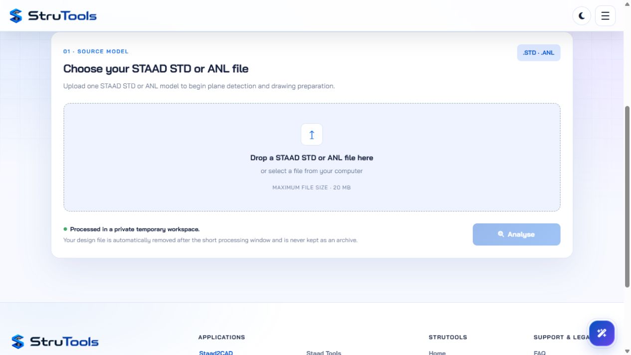
Choose one STD or ANL file. No drawing is generated until you select Analyse. 2 — Confirm the File
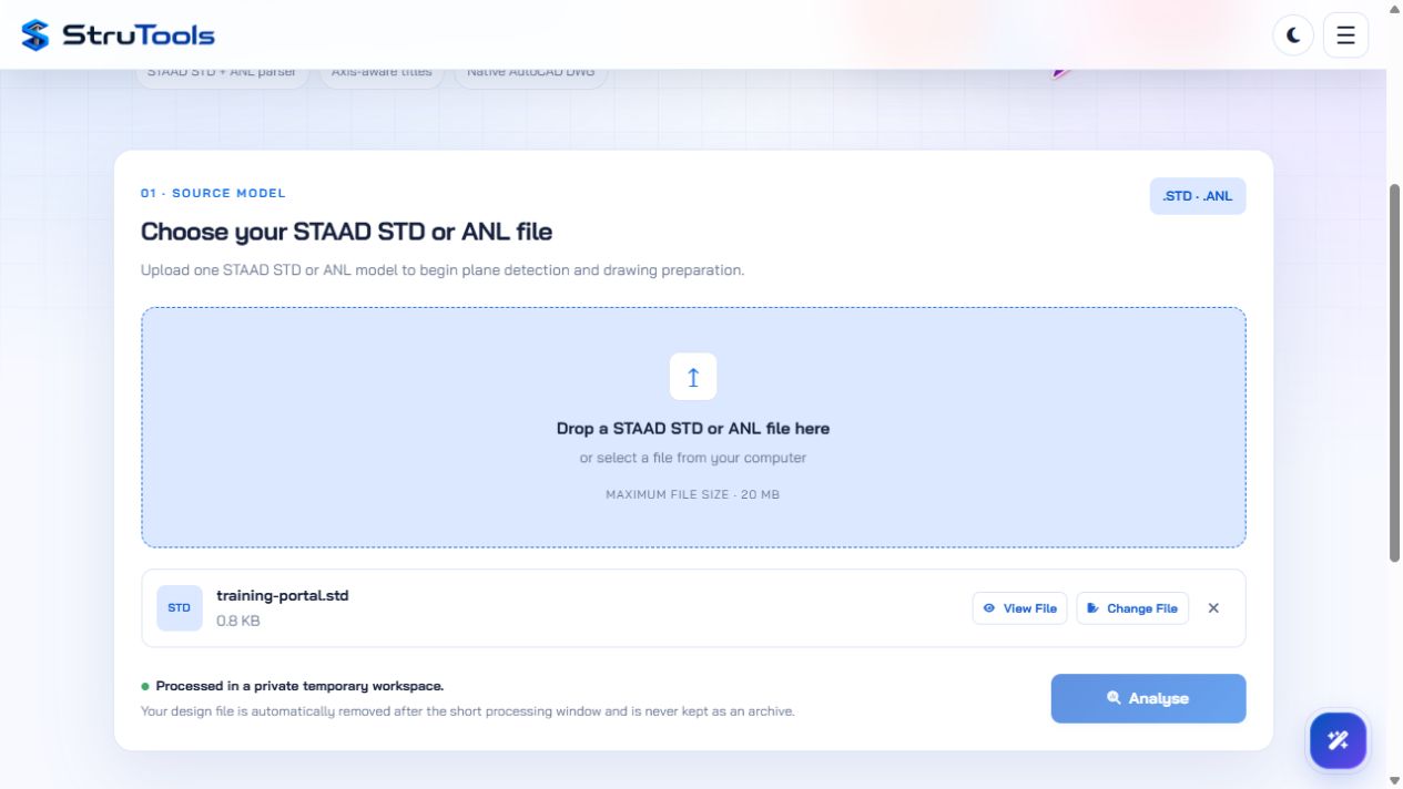
Check the filename, inspect it if needed, then select Analyse. 3 — Check the Model and Planes
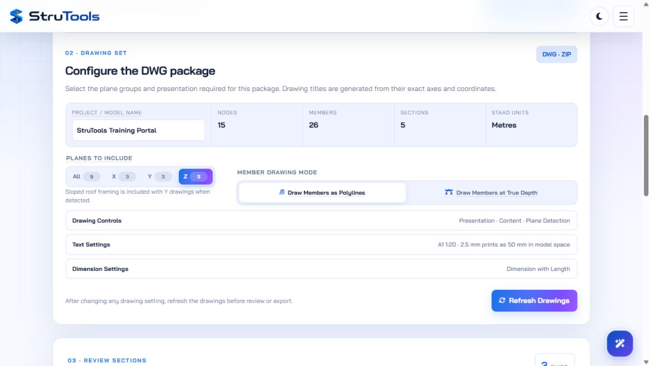
Compare the model summary with your source. Z drawings are selected initially; choose Y to include a detected sloped roof plan. 4 — Review a Frame
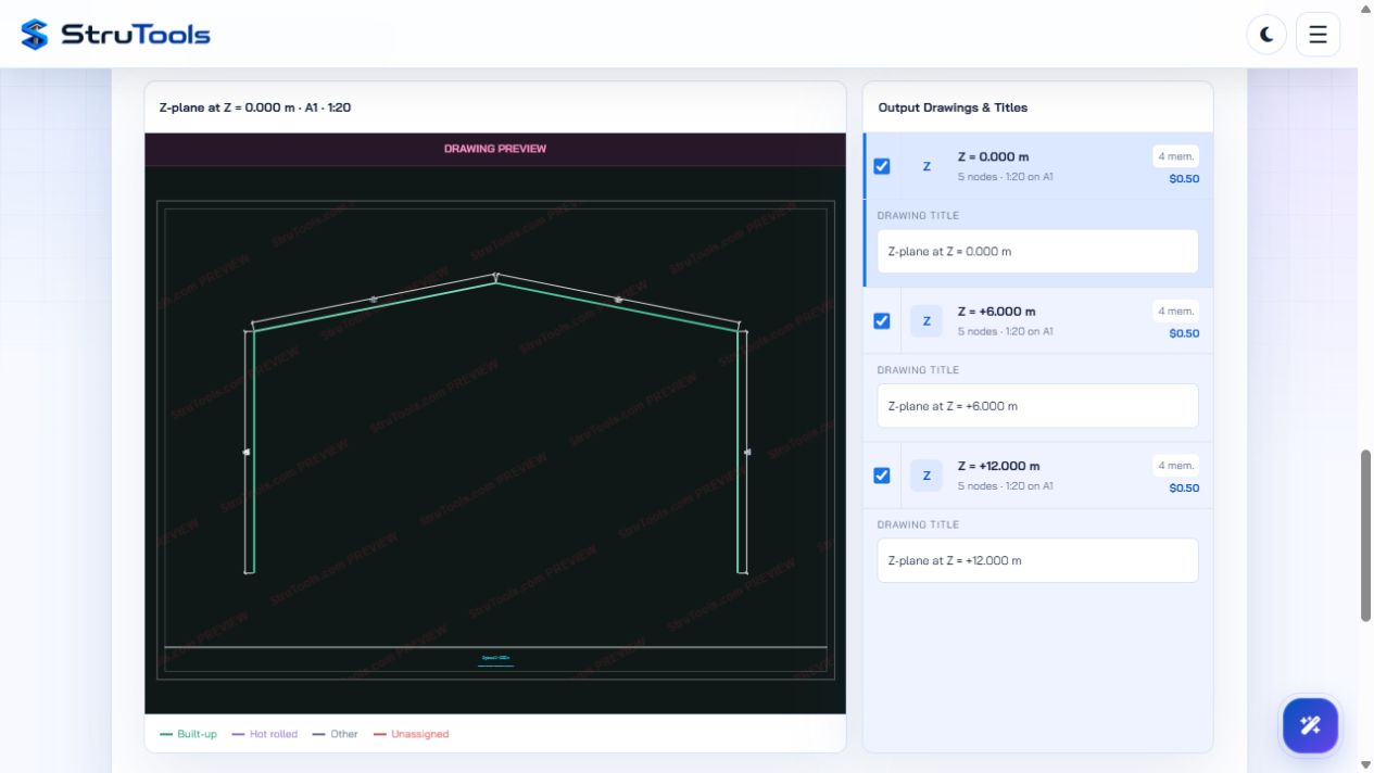
Click a drawing name to preview it. The small checkbox controls whether it belongs in the export package; clicking the name does not change that selection.
Select a screenshot to enlarge it. These are real application captures; playback advances through the recorded steps.
3. Choose the Drawing Planes
The axis identifies the coordinate held constant for an ordinary plane. X drawings show Z horizontally and Y vertically. Y drawings show an X/−Z plan. Z drawings show X horizontally and Y vertically. Do not read the axis letter as a drawing number or a promise that every model has a useful sheet in that group.
Z is selected initially. Select X, Y or All as required, then refresh. The axis counts describe available planes, while the review filter only shows axes generated in the current drawing set. For this example, the three Z elevations are at 0, 6 and 12 m. Selecting Y also includes the detected Sloped Roof Framing drawing. That special plan is rotated to place model Z horizontally and model X vertically. After changing axes, check the export checkboxes again: newly generated sheets may not yet be selected.
4. Choose Centreline or True Depth
| Mode | What It Shows | Export Route |
|---|---|---|
| Draw Members as Polylines | Symbolic member lines; the line width is a presentation setting, not a general section-depth check. | Currently free with a 100% discount. |
| Draw Members at True Depth | Projected section outlines using recognised section dimensions and orientation. | Paid per selected drawing at the displayed current price. |
Start with polylines if you mainly need a clean framing layout. Use true depth when checking the displayed section shape matters. Recognition and orientation still need review: do not infer that an unrecognised property is correct simply because a member is visible. The drawing-controls guide compares the presentation choices and explains the true-depth options.
5. Refresh After Changes
After changing drawing axes, presentation or text settings, select Refresh Drawings. The existing preview is deliberately treated as out of date until regeneration finishes, and payment/export is unavailable during that state. Wait for the refreshed preview before deciding that a setting has had no effect.
6. Review, Name and Select Your Sheets
- Use Find Drawing and Drawing Type to narrow the list. Filtering is not the same as removing drawings from the package.
- Select and Clear act on visible rows. Clear All removes every selection, including rows hidden by a filter.
- Use the checkbox beside each drawing to include it, and its name to switch the preview.
- Edit Project / Model Name and individual Drawing Title fields when needed, then refresh if prompted.
- A highlighted sparse level is a request for review, not proof that the drawing is wrong. Check its members before including it.
- The public preview is watermarked. Admin-only zoom and test-download controls are not part of this public workflow.
7. Review the Total and Download
For centreline mode, select Export, check the selected drawing count and continue to download. No card details are required. Optional support after download is a tip for the free tools, not a condition of getting the package.
For true-depth mode, check the current per-drawing price and selected count before continuing to Stripe Checkout. Enter payment details only on the secure Stripe page. The package is released after payment is confirmed. If the payment window is blocked, allow the checkout popup; if payment is not confirmed, do not assume the export has completed. No real payment is needed to follow the free tutorial example.
Review the Free Export
This capture shows the free route, not a paid-checkout bypass.
Confirm Your Selected Drawings
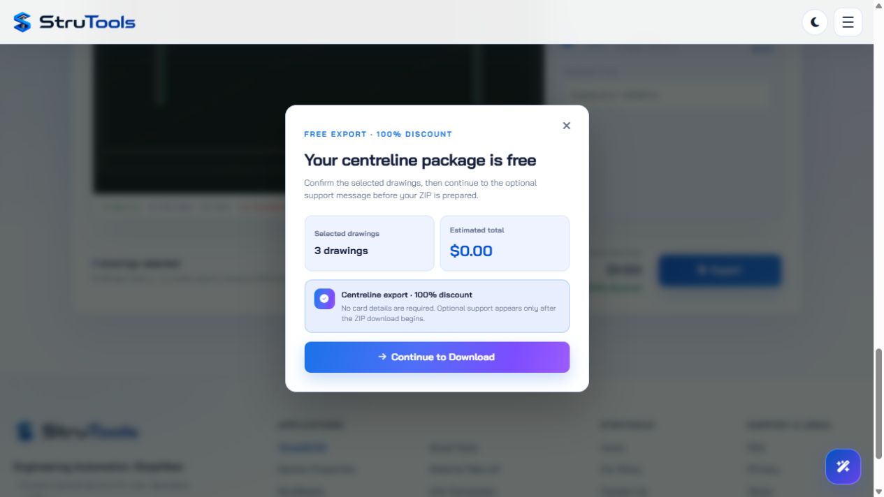
Check the drawing count and the zero total, then select Continue to Download. For true-depth drawings, the review instead leads to paid Stripe Checkout.
Select a screenshot to enlarge it. These are real application captures; playback advances through the recorded steps.
8. Open and Check the DWG Package
Extract the ZIP. The DWG folder contains the selected drawings and README.txt explains the plotting setup. Model geometry is written in millimetres at 1:1; the A1-ratio border is sized for the stated plot scale. This is not a reason to scale the model geometry again. The current compatibility profile is AutoCAD 2013 DWG, and dimensions are native editable CAD dimensions.
- Confirm the drawing count matches your selection.
- Check a known span, bay length and level against the source. The training example uses 12,000 mm span and 6,000 mm bays.
- Check member sizes, drawing titles, view direction and layers.
- Plot the border at the stated scale and check text readability.
- Keep the source model revision with the checked output. Export does not constitute engineering approval.
If Something Looks Wrong
| Symptom | Check First |
|---|---|
| ANL does not load | Confirm it includes the numbered model input, not just analysis results. |
| Expected drawing is absent | Check selected axes, then refresh. Review plane tolerance and minimum members in Drawing Controls. |
| Export is unavailable | Refresh changed settings and select at least one drawing. |
| Roof does not follow the selected label mode | Read the roof guide: its presentation is intentionally fixed. |
| Missing or unclear sizes | Review source property assignments and Model Review Notes before changing text appearance. |
| Checkout does not open | Check the popup permission and the message shown by the application; do not share card information in an error report. |
Continue with Drawing Controls and Presentation or Roof Framing. For the broader engineering handoff, keep using our original STAAD-to-AutoCAD conversion guide and model-to-drawing workflow.
This article provides general educational information. Project-specific structural design, calculations and drawings should be reviewed by appropriately qualified engineering professionals and checked against applicable project requirements and standards. StruTools does not replace engineering judgement or professional design review.