Tutorials
Staad2CAD Drawing Controls: Labels, Dimensions and True Depth
Choose a readable drawing presentation, understand true-depth settings, and control text, dimensions and schedules with real application examples.
A readable drawing starts with choosing what information the sheet needs. Staad2CAD provides different ways to show section sizes, member lengths and schedules without changing the source model. Follow the first-package tutorial first if you have not yet uploaded a model.
Choose Member Sizes Presentation
| Option | Use It When | What to Review |
|---|---|---|
| Dimension with Length | You want member sizes and lengths communicated through member-length dimensions. | Check readability where several members meet; grid/overall dimensions are a separate choice. |
| Text Near Members | A relatively open frame can carry sizes close to the steel. | Check long size descriptions and neighbouring members. |
| Text with Leaders | Labels need to sit away from crowded geometry. | Check leader destinations, wrapping and arrow style. |
| Member Marks + Size Table | Repeated or lengthy section descriptions make the frame crowded. | Match each mark to its schedule row and confirm the selected frame. |
| No Text | You need clean geometry to continue drafting in CAD. | Members and the title block remain; the main title remains unless its own height is zero. |
Change one setting, select Refresh Drawings and inspect the same frame. Comparing different drawings at the same time can hide what the control actually changed. For a non-roof sheet with more than 100 nodes, the application can suggest Member Marks + Size Table once per uploaded model and highlight that control. It is guidance, not an automatic change to your chosen presentation.
Switch from Length Dimensions to a Schedule
Public interface · Same training model · Verified 19 September 2026
1 — Open Drawing Controls
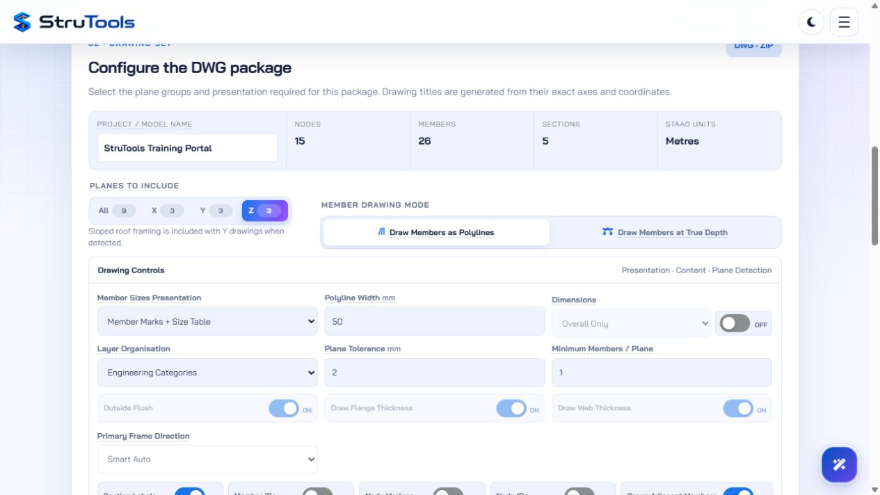
Find Member Sizes Presentation. Select Member Marks + Size Table, then refresh the drawing set. 2 — Inspect the Schedule Result
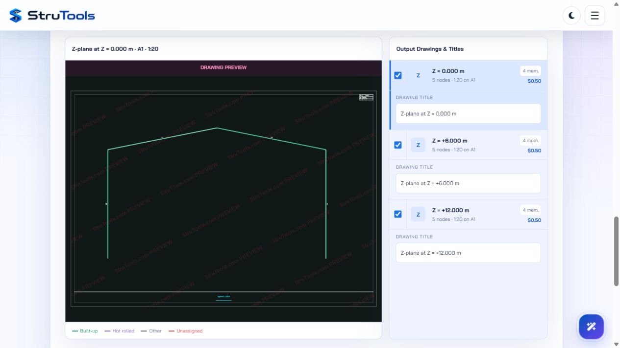
The frame uses short marks; their full section descriptions appear in the table. Review the frame and schedule together. 3 — Compare No Text
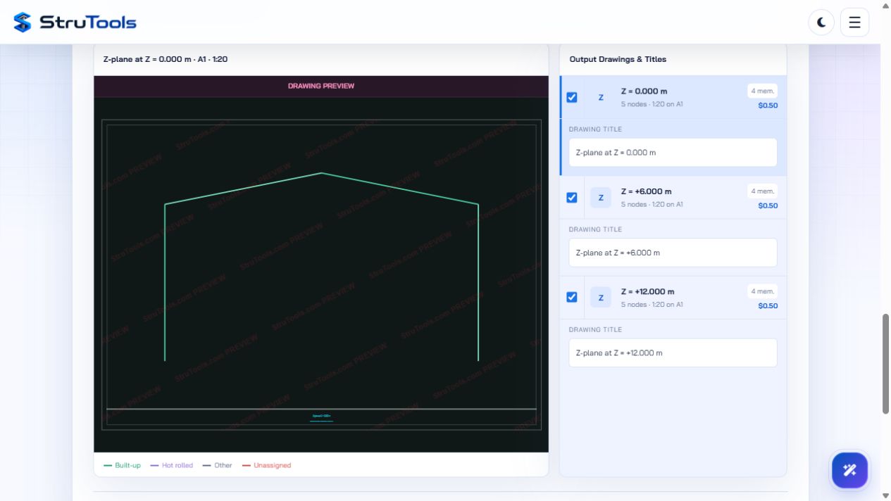
Select No Text and refresh the same ordinary frame. Member annotations, node markers, schedules and dimensions are omitted.
Select a screenshot to enlarge it. These are real application captures; playback advances through the recorded steps.
Understand True-Depth Controls
Draw Members as Polylines is a symbolic layout mode. Its Polyline Width does not generally represent the physical member size. Draw Members at True Depth uses recognised property dimensions and their projected orientation. BETA and the viewing plane matter: an I-section seen from its flange side must not be interpreted as its full web depth.
- Outside Flush aligns applicable connected member outlines on a consistent outside face; review the result at roof and wall junctions.
- Draw Flange Thickness adds flange detail where the section and view support it.
- Draw Web Thickness shows web-thickness detail, including hidden lines in appropriate flange-side views.
- Primary Frame Direction can use Smart Auto, XY Frame (view Z), or YZ Frame (view X). Choose deliberately when the automatic orientation does not represent the intended primary frame.
- Group Adjacent Members groups eligible collinear members for drawing clarity. Always check that the representation still communicates the intended changes in section.
Review True Depth Before Export
The preview is not a structural design verification or a paid download.
True-Depth Frame Preview
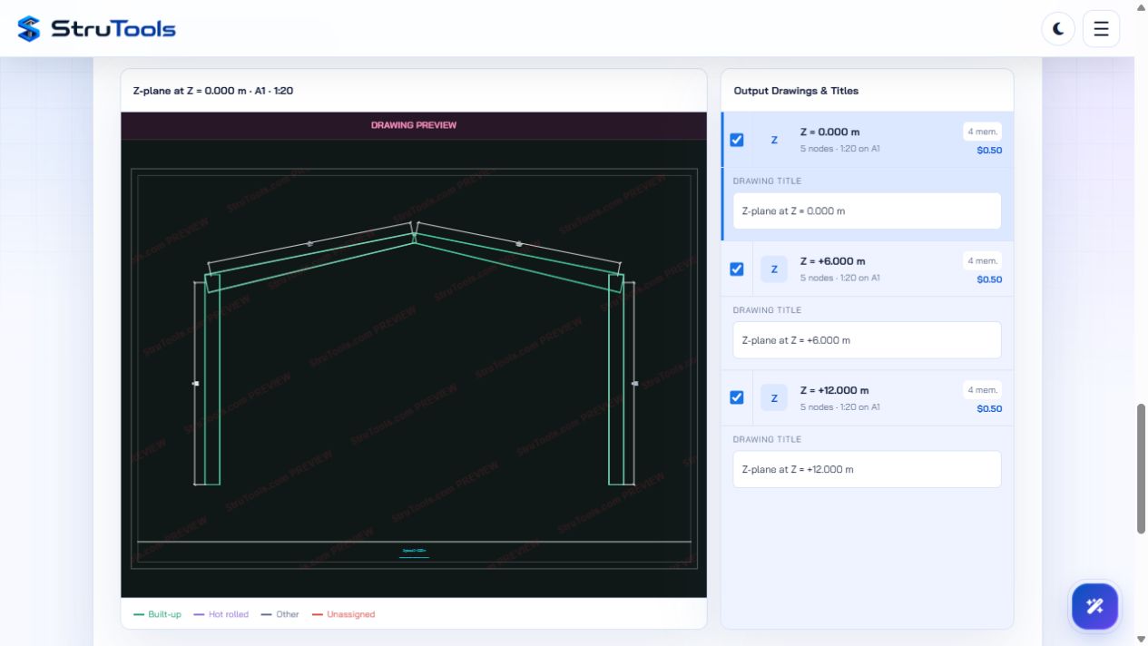
Compare the taper direction, column/rafter junctions and section outlines with the source. True-depth export follows the paid route at the current displayed price.
Select a screenshot to enlarge it. These are real application captures; playback advances through the recorded steps.
Text Settings: Printed Size, Not Model Size
Printed Text Height and Printed Title Height describe the intended paper size. Staad2CAD calculates a corresponding model-space size from the sheet scale. Increasing model extents does not mean you should manually multiply the printed-height input by the building length. Arial Narrow is the default font; use the shared font choice rather than expecting separate dimension-font controls.
Text Width Factor, Oblique Angle, Member Clearance and Wrap After Characters adjust legibility. Start with the defaults, then change only the setting relevant to the problem. Very short wrapping can make a label unnecessarily tall; a large clearance can move it far from its member. Leader Arrow Style applies to Text with Leaders.
| Setting | Effect |
|---|---|
| Printed Text Height = 0 | Valid input: omit general text without rejecting generation. Independently enabled geometry and dimension settings still have their own rules. |
| Printed Title Height = 0 | Omit the main drawing title without suppressing the members or border. |
| No Text presentation | On ordinary drawings, suppress the wider annotation set, including node markers, schedules and all dimensions. This is more than setting one height to zero. |
Control Dimensions and Units
The Dimensions switch adds overall dimensions or Overall + Gridlines. The default Dimension with Length presentation separately creates member-length dimensions, so switching off overall dimensions is not the same as requesting no dimensions anywhere. Use No Text for a genuinely clean ordinary sheet.
Dimension Settings control displayed units, rounding, arrows, printed text height, offset, extension gap and colour. Geometry remains in millimetres at true model scale even when the dimension display is set to metres. Millimetre dimension text intentionally has no mm suffix; other unit suffixes remain where applicable. Keep the unit basis clear in your project documentation.
Spacing is initially calculated for the sheet. A manual offset or extension-gap edit retains your chosen spacing for later refreshes. Check extension lines and neighbouring annotations in the regenerated result; an unusually large offset can use more sheet space rather than solving the source of the clutter.
Plan Labels, Drawing Content and Layers
On Y-axis plans, repeated eligible members of the same section in one bay can share one representative size or mark followed by (TYP). The prefix is the actual value, not a fixed HRI label. All member geometry stays present. This simplification does not apply to ordinary elevations.
Section Labels, Member IDs, Node Markers and Node IDs serve different purposes. Turn on identifiers when checking the source, then decide whether they belong on the issued drawing. Layer Organisation offers Engineering Categories or Single Member Layer. Review downstream CAD editing and plotting requirements before choosing the simpler organisation.
If a Plane Is Missing or Too Sparse
Plane Tolerance groups near-coincident coordinates; Minimum Members / Plane filters small groups. These are model interpretation controls, not cosmetics. Confirm the correct axes first. Increase tolerance only after checking the actual coordinate discrepancy, because an excessive tolerance can combine levels that should be distinct. Lowering the minimum can reveal small valid frames, but it can also add sheets you do not need.
- Compare the same sheet before and after a change.
- Refresh before judging the result or exporting.
- Check schedule marks against the sizes they reference.
- Check units, overall dimensions, taper direction and view orientation.
- Review the exported DWG and its printed scale, not only the browser preview.
- For roof-specific exceptions, use the dedicated Roof Framing guide.
Continue with Roof Framing in Staad2CAD. The original model-to-drawing workflow remains useful for revision control, engineering review and the handoff beyond the converter.
This article provides general educational information. Project-specific structural design, calculations and drawings should be reviewed by appropriately qualified engineering professionals and checked against applicable project requirements and standards. StruTools does not replace engineering judgement or professional design review.