Tutorials
Roof Framing in Staad2CAD: Y Drawings, Marks and Size Tables
Generate and review a sloped roof-framing plan, understand its fixed presentation, and learn why its labels differ from ordinary frame elevations.
A pitched roof does not sit at one Y elevation. Its eaves and ridge have different heights, so ordinary constant-level plans cannot describe the complete roof on their own. Staad2CAD adds a special Sloped Roof Framing drawing from a detected connected upper surface, and places it in the Y drawing group.
Generate the Roof Plan
- Upload the model and select Analyse.
- In Drawing Planes, select Y or All. Leaving only the default Z group selected will not include the special roof plan.
- Select Refresh Drawings and wait for the new set.
- Filter Drawing Type to Y Drawings if useful, then select Sloped Roof Framing in the output list.
- Review the roof, its schedule and the export checkbox. Selecting its name only changes the preview.
Include and Review Roof Framing
Recorded on 19 September 2026 · Same sample, different drawing group
1 — Include the Y Group
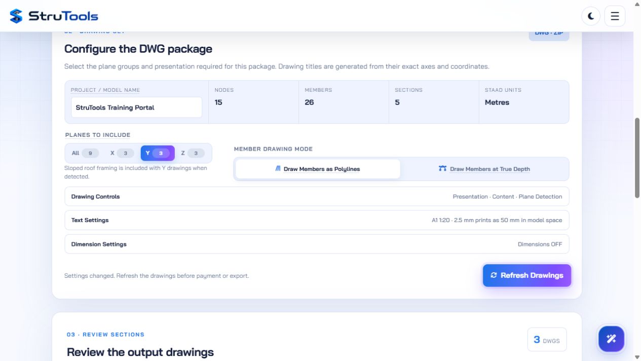
Include Y and refresh. The roof is generated when the model meets the roof-detection conditions. 2 — Open Sloped Roof Framing
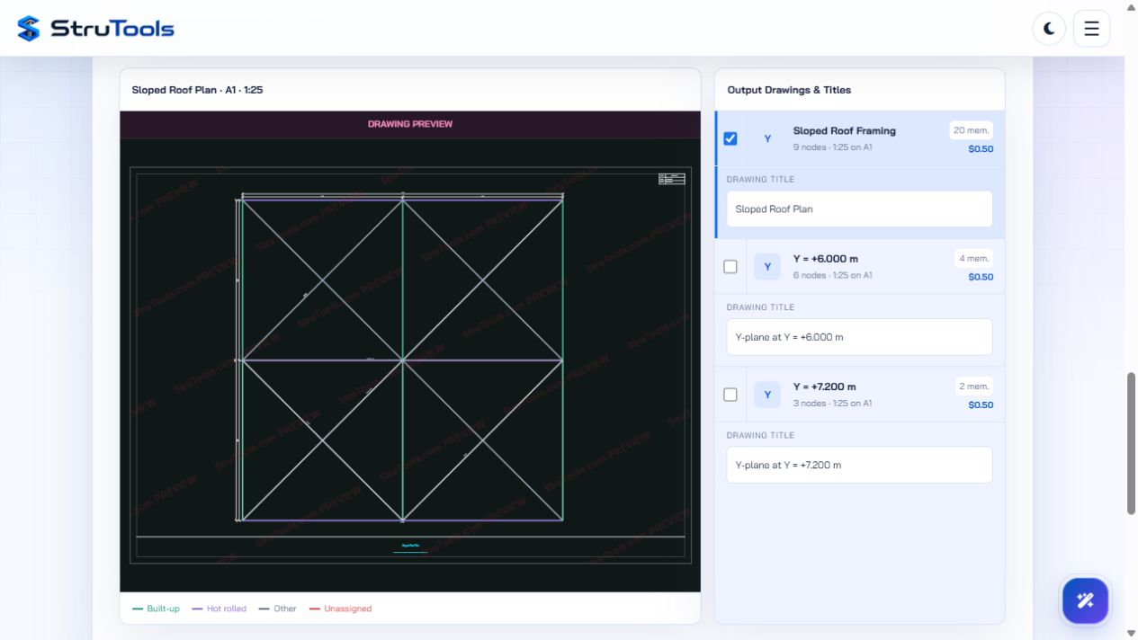
Review the complete member layout, top/left grid chains and the mark-to-size table. The sheet uses its roof-specific presentation.
Select a screenshot to enlarge it. These are real application captures; playback advances through the recorded steps.
What Roof Detection Looks For
The current detector considers the highest nodes at each X/Z location, looks for connected members between those nodes, and checks that the candidate has real slope and extent in both plan directions. A flat floor is not automatically a sloped roof. A single isolated two-dimensional frame is also not a complete roof surface.
It currently chooses one qualifying connected roof surface, favouring the one with more members. Separate disconnected buildings or unusual multi-roof models therefore need particular care: one generated roof sheet should not be read as proof that every roof area has been included. Check the source connectivity and the preview against the model.
The special roof view places model Z horizontally and model X vertically. Ordinary Y level drawings use X horizontally and −Z vertically. Check that view orientation before comparing the roof with a conventional floor plan or external CAD reference.
Understand the Fixed Roof Presentation
The detected roof sheet currently fixes Member Marks + Size Table and overall/grid dimensions, with grid chains on its top and left sides. This applies only to that roof sheet. Ordinary X, Y and Z planes continue to follow the normal presentation controls.
Consequently, changing Member Sizes Presentation to No Text or Text Near Members does not replace the roof's fixed schedule mode. This does not mean every control is ignored: the selected drawing mode, font, text heights and other retained settings still matter. Zero general text height can suppress the schedule text, and zero title height can suppress the main title. Use the controls guide to distinguish these settings.
Which Members Receive Labels?
All detected roof-member geometry stays in the drawing. The annotation set is deliberately smaller: projected diagonal members are eligible, and recognised tube, pipe, hollow and angle sections are eligible even when horizontal or vertical on the sheet. Ordinary horizontal and vertical frame-member labels are omitted because the frame views already describe them.
Do not interpret a missing label as a missing member. Check the geometry first. Roof marks use the shared section groups, including HRT for hollow/tube sections and HRP for pipe/CHS sections where recognised. Marks identify schedule entries; they are not automatically the original STAAD member numbers.
Repeated eligible members with the same section within a plan bay can use one representative mark followed by (TYP). The actual mark or size is used; it is not a universal HRI (TYP) note. The schedule describes the displayed eligible sections, not a complete material take-off of every member in the building.
Check Before Exporting
- Y was selected and the drawing set was refreshed.
- Both roof slopes and the intended bays appear in the geometry.
- The view orientation and known bay dimensions agree with the model.
- Eligible marks are readable and match their schedule rows.
- Repeated (TYP) notes have the intended scope; unlabelled frame members are still present.
- The selected export mode and drawing count are correct.
- The DWG plot scale and output are checked before project use.
The more-than-100-node suggestion is intentionally excluded for detected Roof Framing, because this sheet already has a fixed schedule presentation. Its absence is not an indication that the roof is small or that the output requires no review.
If the roof is missing, start with Y selection, refreshed drawings and source connectivity. Do not increase plane tolerance indiscriminately or move model nodes just to force a roof sheet. For drawing issue and revision coordination beyond Staad2CAD, see the existing Structural Model to CAD Workflow.
This article provides general educational information. Project-specific structural design, calculations and drawings should be reviewed by appropriately qualified engineering professionals and checked against applicable project requirements and standards. StruTools does not replace engineering judgement or professional design review.